Since all rolling stock is built on top of a common car base, here's how that base is built:
| I purchased my end sills from Comstock Carshops off of Ebay (AFAIK, they are not available from Comstock's Website). A set of end sills includes two white metal cast end sills, two pockets, a drawbar, and two straight pins. | 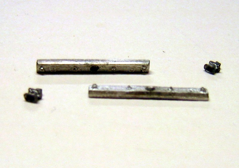 |
| As each car will have four torsion rods and the end sill is cast with two NBWs, two additional 2 ½" Grandt Line NBWs are added to model the additional end bolts. Assembly consisted of using a small drill and pin vise to ensure a good fit between the pocket and end sill and using CA as an adhesive. | 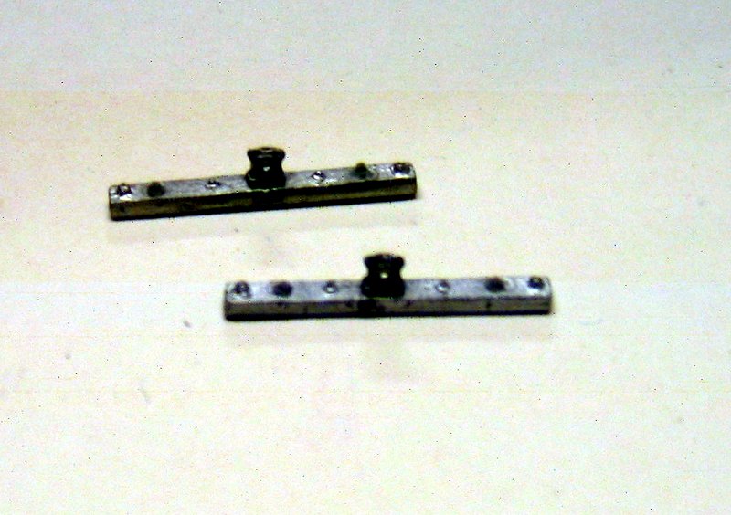 |
| The outside of the wooden frames are constructed from two 8"x8" pieces of lumber for the long members and two 6"x8" pieces of lumber that will be adjacent to the end sills. The length of the 6"x8" pieces is determined by the length of the end sills, filing down the wood pieces to fit. | 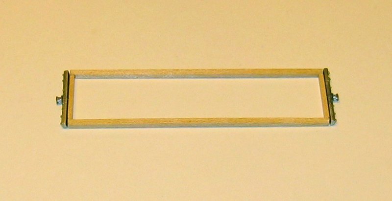
|
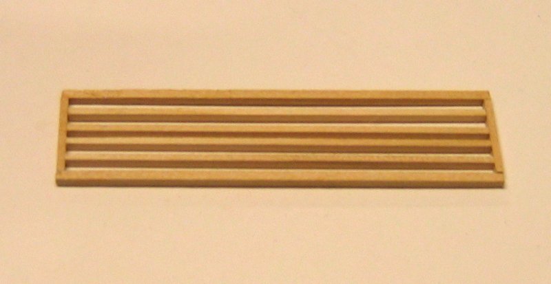
| The inside beams are four 6"x8" pieces cut to fit with 10"x8" stock used as spacers and removed after the inside beams are glued in place. |
|
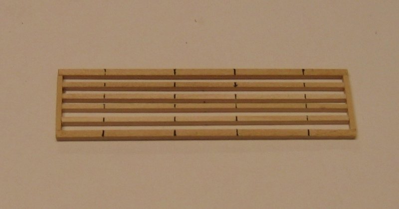
| At this point, the center line is marked on the top side of the frame, and locations of the torsion bar support beams and truck beams are marked on the bottom of the frame, and the location of torsion rod holes on the ends of the frame. | 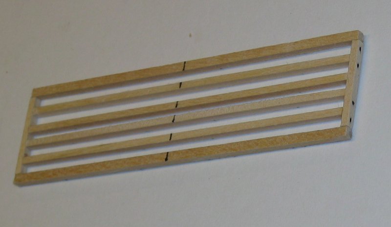
|
| The ends of the frames are drilled out with a #67 size bit in a pin vise. This allows for the torsion rods to have extra play to avoid binding during installation later. | 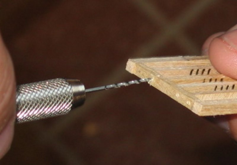
|
| Next add six feet of deck flooring centered on the frame’s center line to the top of the frame. This will provide support for the brake system. After cutting the 2"x12" stock to length, final trim is done using sandpaper and micro files. | 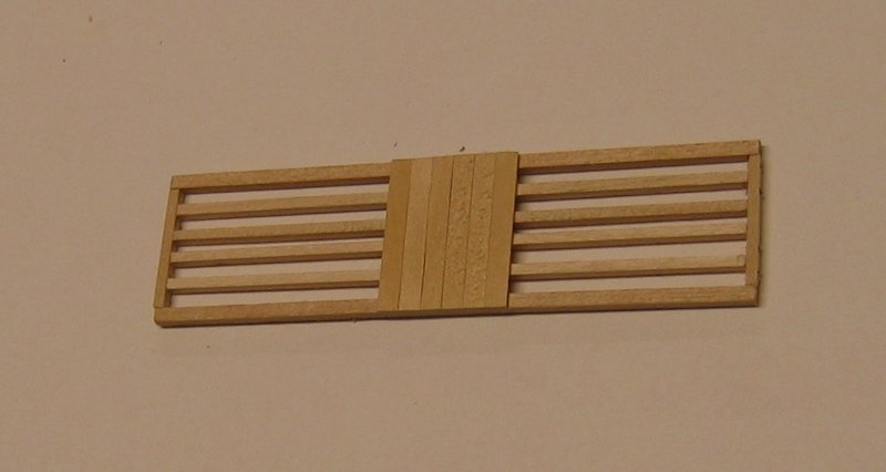
|
| Now the brake system can be added. I used Westinghouse brakes from Grandt Line, which consists of the necessary parts for Type K breaks. Here's a picture what you get in the kit. Obviously, there are a lot of parts and Grandt’s instructions are pretty cryptic about what exactly goes where. Many thanks go to Fred Carlson who worked with me to figure out how all these parts should be used. | 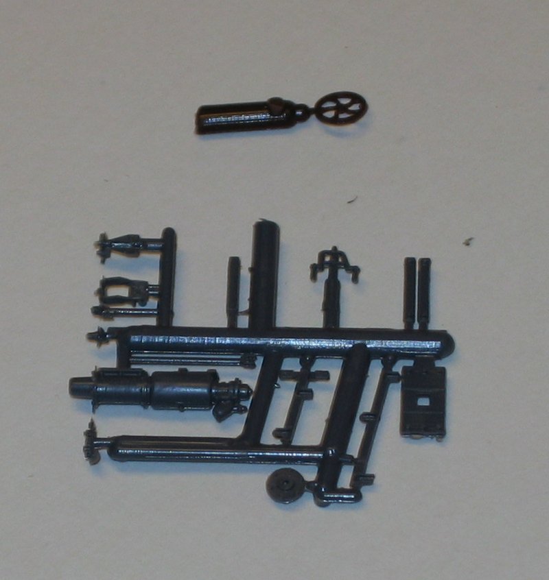
|
| Brake rods are modelled with 0.015" piano wire. First the brake cylinder rod/clevis is attached to the cylinder and reservoir assembly. | 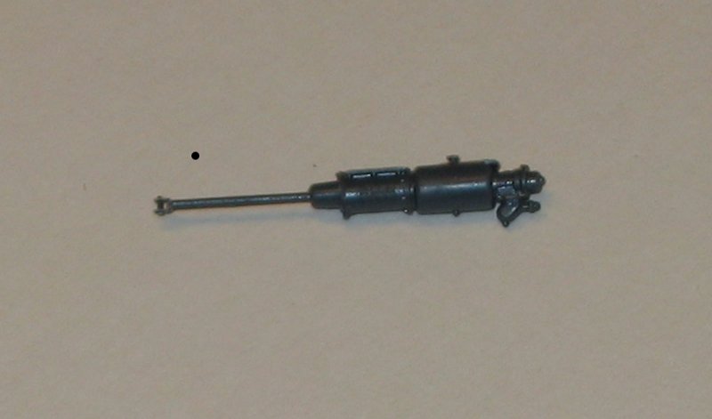
|
| This assembly is mounted to the underside of the center floor section. | 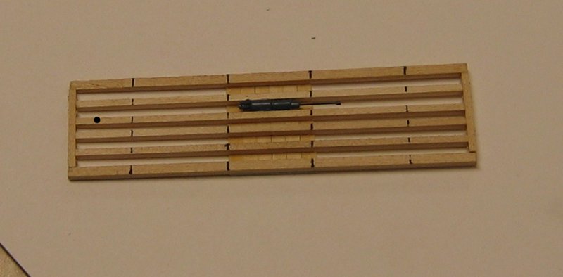
|
| Next attach the long and short brake levers to a rod | 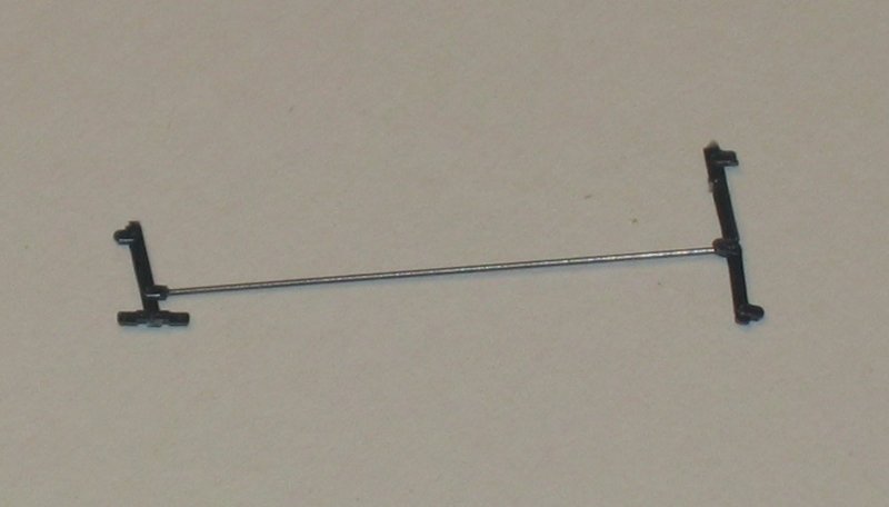 |
| The lever sub-assembly is mounted to the underside of the frame, mating the end of the clevis to the long brake lever such that the rod is parallel to the frame beams. | 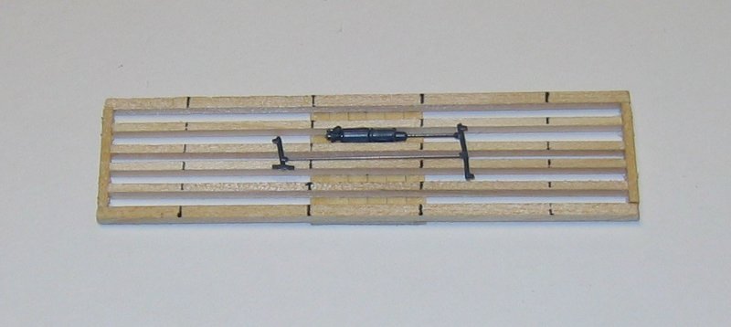 |
| Air hoses are modelled with 0.028" brass wire. First, the air hoses from the reservoir are added. |  |
| Now add the main hose run. Trimming will be done when gladhands are added. | 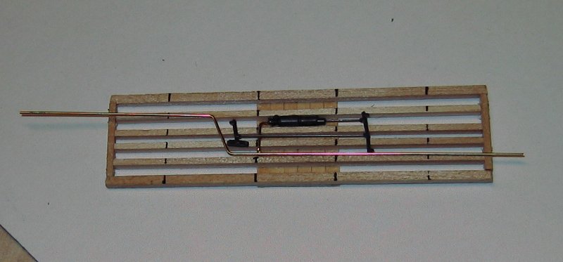 |
| The torsion support beams are constructed from 4"x10" stock cut to fit the width of the frame. Notches are filed to allow these beams to clear the brake rods and air hoses. Lastly, a #67 bit was used to drill holes in the edge of the beams for the torsion bar V brackets. While I was able to find plastic V brackets, I decided to make mine from 0.028 brass wire to provide better support. | 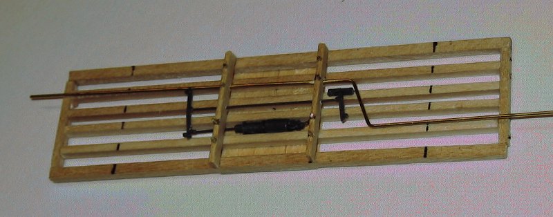 |
| The torsion rods are modelled with more 0.028" brass wire. Each car gets four of these, so take your time and use the end sill holes to help adjust the fit. Once in place, each torsion bar gets a Precision Scale turnbuckle attached to the center of the rod. | 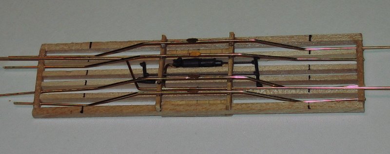 |
| Truck beams are constructed out of 8"x10" stock cut to fit the frame width. As with the torsion support beams, notches are filed to ensure the truck beam clears the air hoses and torsion rods. A 1/16" pilot hole is drilled in each truck beam for mounting the truck. Once the truck beams are in place, the 0.015" piano wire rods from the small and large brake levers to the trucks are added. Lastly, the hand brake rod is added and just left open at this point – the brake chain will be added later. | 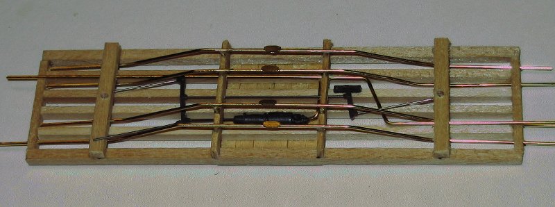 |
| The ends of the torsion bars are filed off so that they no longer extend past the ends of the wooden frame, and then attach the end sills. | 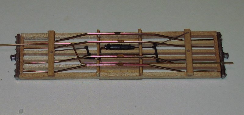
|
| The attached end sills now act as guides for trimming the air hoses so that the Precision Scale glad hands fit appropriately. | 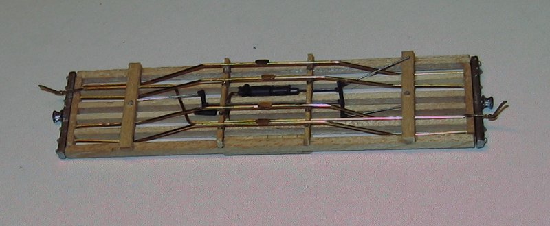 |
| Blackstone Models arch bar trucks are now attached. A scale 6" piece of 3/32" ABS tubing provides a clearance spacer. | 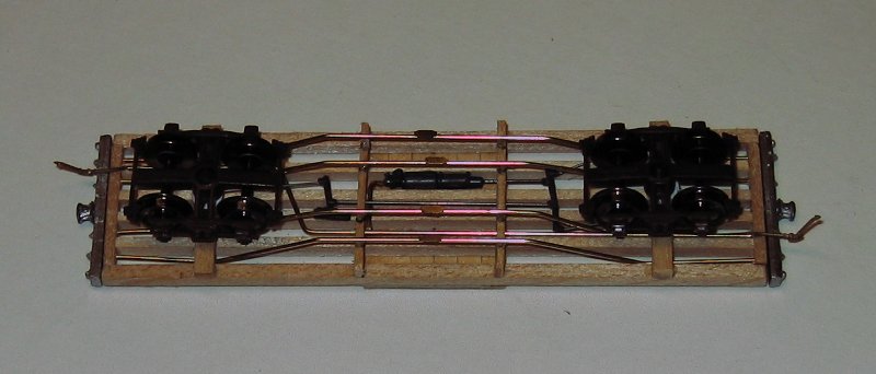 |
| Finish the decking with more 2"x12" stock, sanded down to proper size and the outside floorboards further shaped as necessary to fit to the end sills. | 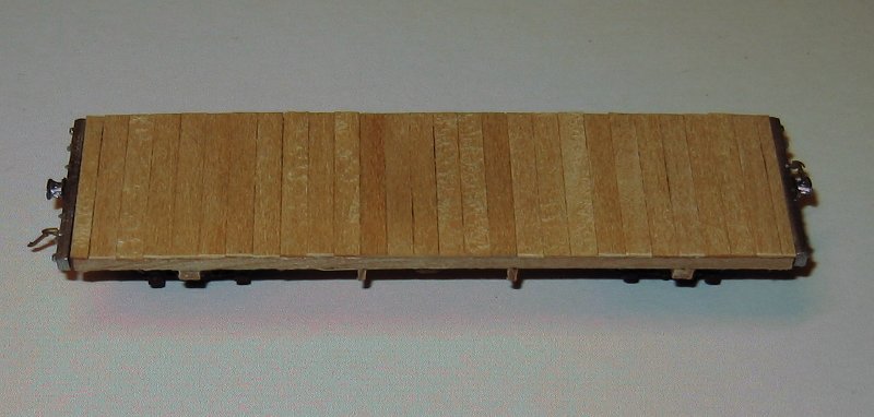 |
| Add the chain roller bracket and lower stave bracket. | 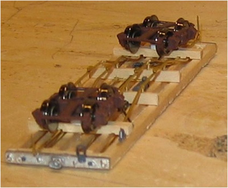 |
| Add two Grandt NBWs to the truck beams to model the support rods. | 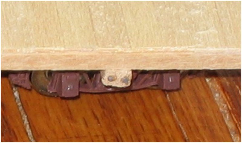 |