Starting Point
As viewed from the bottom of the stairs - I did mention that the land deal was for the tops of the cabinets, didn't I?
Replaced Scaffolding
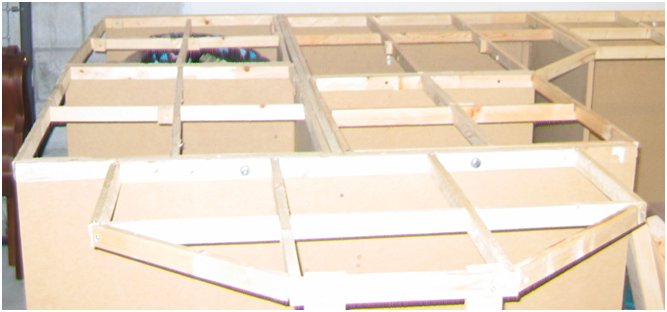

Subroadbed
The subroadbed was contructed using the "cookie cutter" approach to minimize the number of splines. I decided to go "whole hog" and use 1/2" 9-ply cabinet grade plywood.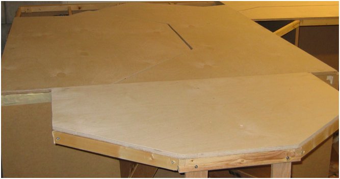
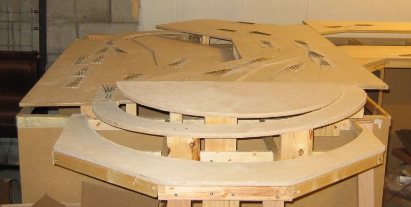
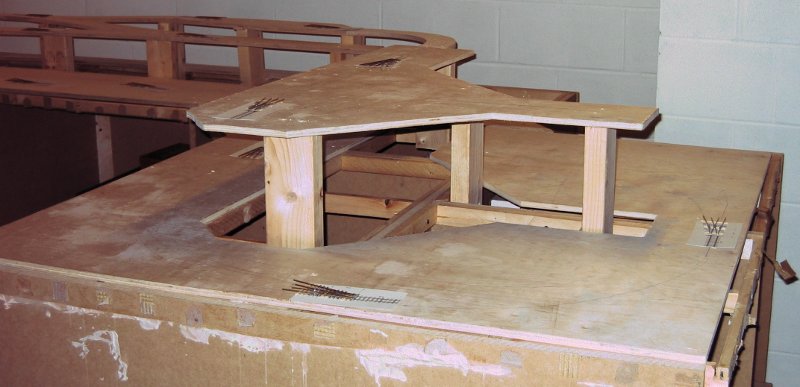
The initial track plans are then penciled onto the plywood and cutouts marked for removing extra pieces. Then I used 2”x2” and 2”x4” segments for vertical support. These segments are attached to both the plywood and the lattice or cabinet via more countersunk screws. Grades are constructed by fixing the plywood at each end and letting the wood find its natural slope and then backfilling with support elements. In addition to the major slope changes, the Lower and Upper Blackhawk yards include smaller altitude changes to capture the feel of mountain railroading.
Track Laying: Philosophy and Initial Steps
I decided to use a slightly different track laying process from the usual approach of transfer plan to benchwork , install the roadbed, stain/sand/restain ties, and then lay trackwork. Instead, I assembled track before installing the roadbed and used the track to guide where the roadbed would be laid. Also, I decided to stain ties before attaching them to the roadbed so that I could avoid the sanding step (and all of the resulting dust).As a result, I was able to use my track jigs with a minimum of modification by letting the track as constructed drive the final placement of the roadbed. I wasn't too worried about misalignment because this is an early mountain railroad after all! Ballasting misalignments would re-create non uniform grading width, places where ties are exposed from the ballast, and places where ballast has begun to erode away.
All tracks are hand laid using FastTrack or home-made jigs. Turnouts and bridles use 22” tie spacing while the rest of the track uses 24” tie spacing. PCB ties are used every scale 12 feet (or so) to provide support for keeping the track in gauge and to provide multiple points for dropping feeders. PCB Joints between rail segments are overlapped for additional strength, except when attaching track runs to turnouts.
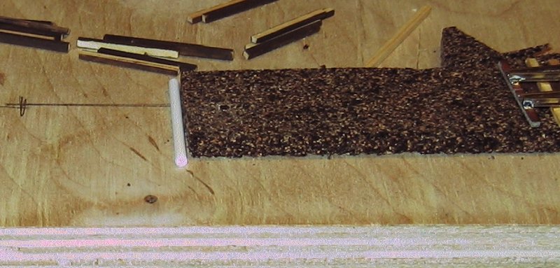
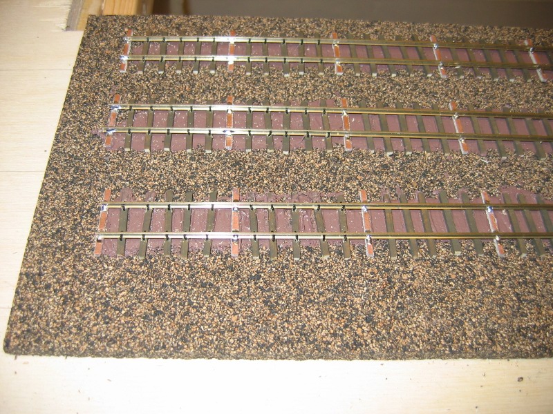
Cork for roadbed has always been my personal favorite. I decided on HO scale cork sheets for yards and turnouts and N scale cork profile for track runs. Because there is a difference in thickness between the two sources of cork (the sheets are 5mm thick which the N scale cork profile is 3mm thick), I ganged card stock together with spray adhesive to make up the difference in thickness. Besides ensuring a uniform profile, I was able to leave gaps in the paper shims to provides places for adding drainage pipes (I use 3/32” polystyrene tubes that were sanded down on top and bottom to reduce their diameter to 2mm for this).
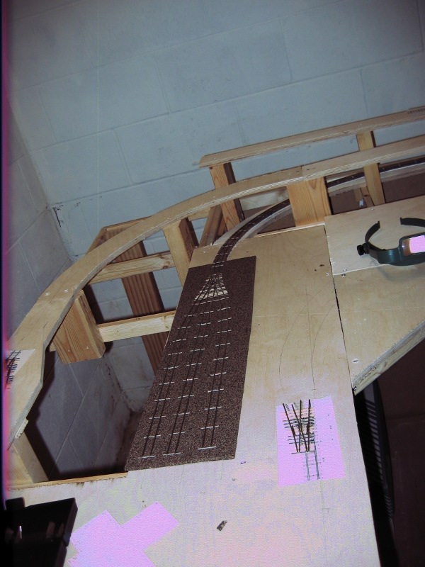
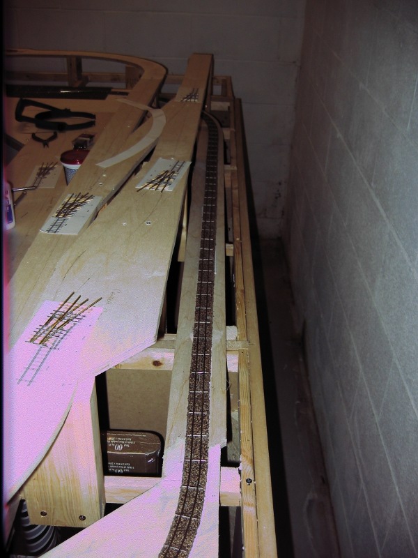
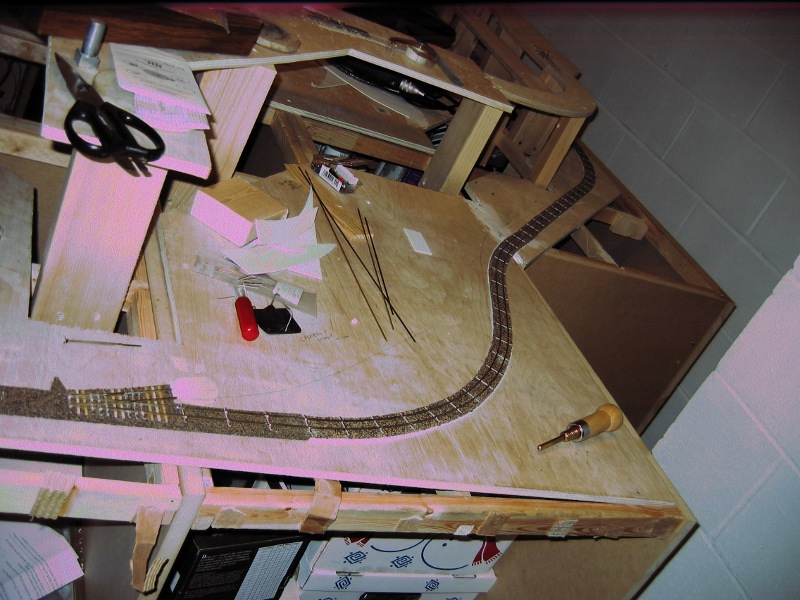
Building the stub turnouts and bridles are their own page and collection of photographs
Bridles throw ties are constructed from 1/32” PCB ties. These ties are cut to the outside gauge of the rail. Then rail joiners are soldered to the PCB tie, using a piece of track as a guide (do not solder rail joiners to the rail). Then trim the rail jointers to the length of the PCB tie using a jeweler’s saw. Finally, notch the top side with a micro file to ensure electrical isolation of the rails.
Before inserting the wooden ties, first drill the access hole for the bridle throw wire through both the roadbed and subroadbed (see the left side of the picture below). Ties are prepared by pre painting three sides of the tie with Floquil’s Rail Tie Brown Enamel. The fourth side is left unpainted as a sanding surface if necessary. This minimizes the amount of generated sawdust. Finally, the PCB ties are attached to the cork with silicone caulk and the wood ties inserted by hand between the PCB ties along the run. Wood ties are not exactly aligned to preserve the feel of early narrow gauge mountain railroading.
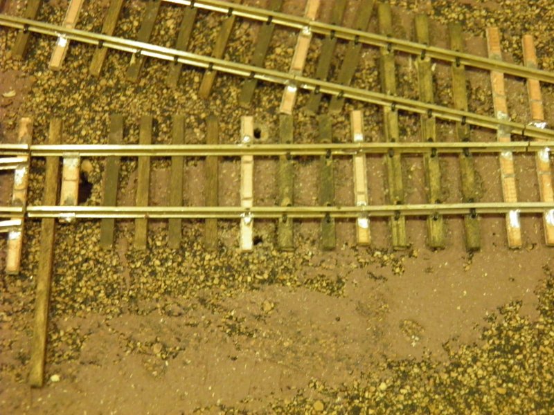
Once all of the wooden ties are in, my next step was to hand spike. Each wooden tie has a minimum of four spikes (one per side of each rail) inserted into pre-drilled holes by hand.
Fascia and pull rods
I decided to use 1/8" hardboard for the fascia and control all turnouts form that single fascia level. This means that in some cases motion has to be transferred almost a foot vertically from the pull knob to the slide switch. In addition, because all of my turnouts are stubs (and some of them are three-way at that) I decided to follow the "move the knob in the direction the bridle should move" convention. If you've read the Turnouts page you'll remember that the bridle wire passes through a fulcrum between the bridle throw bar and the slide switch. So, each linkage between the fascia knob and the slide switch requires another reverse linkage.
I'm making the linkages from 1/2" aluminum U channel, 1/4" dowels and #2 bolts and nuts mounted to some 2"x2" via a #4 screw (the 2"x2" is mounted to the layout via a 2" construction screw. Here's a picture of what the pieces look like and one of the "long" links for controlling an upper turnout.
As far as installing the linkages, here are pictures of one of the long links up to a Central City wye turnout and one of a short link to the Kimber Mill spur:
Spare hardboard is used for places where angles need to be turned between the paddle switch and the reversing link
Pull rods are attached using two pieces of flat aluminum and a couple of #2 screws and nuts. It's probably over-engineered, but at least I know it will work.
Here's what the fascia looks like for lower Blackhawk, along with how the pull rods are arranged in the backing cabinets:
Here are the same set of photographs for upper Blackhawk (the switches in the foreground are power cutoff switches and the one in the background is a polarity switch for the reversing wye leg). As you can see, changing angles in the corner cabinet gets to be interesting:
And for the transition (which includes both parts of Upper Blackhawk as well as the Blackhawk Foundry spots on the lower level
Here's Forks Creek, and the start of both the switch back and the smelter
Here's the switch back, the smelter and the entrance to Central City
Here is Beaver Brook and more of Central City
Lastly, the finish of Beaver Brook and Central City and the Kimber Mill site
Finishing the Fascia and Decorations
To help folks who aren't familiar with the layout, I decided to put up track diagrams identifying all of the sidings and industry spots. These were created with Publisher and printed on stiff report coverstock and the laminated both front and back. They are attached to the fascia with velcro so that folks can pull them off to refer to them.
Since there are a lot of switches and pull knobs on the fascia, I also labeled those by printing labels on the same report coverstock and attaching them to the fascia with double sided tape.
Lastly, the area below the fascia is screened off with simple landscape fabric, held in place with more velcro affixed to the backside of the fascia. You can see all of this at the updated layout tour page