For spacing #4 2-way stubs, I combined the plans provided by Fast Tracks with the bridle drawings referred to above and
made them into a PDF format. I used this for checking spacing during layout planning.
| First cut two pieces of rail to length. Then use the angle notches on the Fast Track jig
to bend the rail to shape. Verify the shape with the turnout jig. |
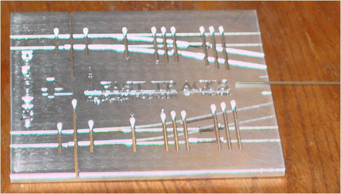
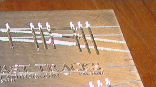
|
| One of the conveniences of the Fast Track system is that they inlude a point forming tool
for filing rails to form both points and frogs. For a stub turnout, only frogs are necessary, so
insert rail into the tool and file the rail end to the proper angle. Then solder the frog points
together using the turnout jig as a guide. |
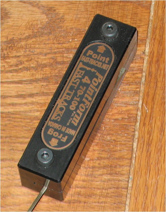
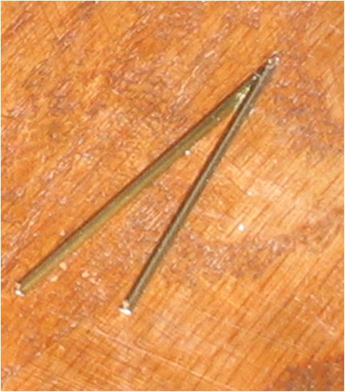
|
| Cut and insert PCB ties into the jig. Do not insert ties past the throwbar as
they won't be used. Using the plans as a guide, file the ties to insure electrical isolation of
the various parts of the turnout. |
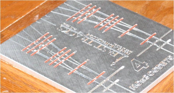
|
| Insert the stock rails, going past the last tie but not past the throwbar.
Pre-bend the diverging route rail to avoid putting too much stress on the solder joints and solder
to the PCB ties. The photograph shows a turnout removed from the jig at this step. |
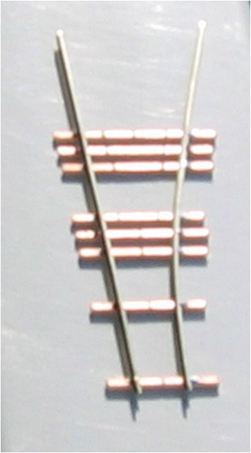 |
| The switch/wing rails are installed up to where the rail touches the stock rails.
where necessary, bend to fit jig curvature. To form the wing rails, nip the rail base and
bend to shape. Then file a relief of the wing rail to minimize tyre rims picking the wing rail.
Then solder to the ties. |
 |
| Next, add guard rails into the jig, ensuring that the guard rail stays flat and being sure
to check clearances with flangeway gauges. |
 |
| Now the frog can be inserted. Confirm gap spacing with a standards gauge or wheelset (or both).
When soldering into place, first ensure that the frog point is flat against the PCB ties.
I prefer to solder the front of the point from the underside of the turnout. |
 |
| When locating the head tie, use the flange gauge to ensure proper space between the
stock and wing rails. When found, step back to the next tie and mark the rails.
Solder the head tie in place and cut/file rails flush to the head tie. |
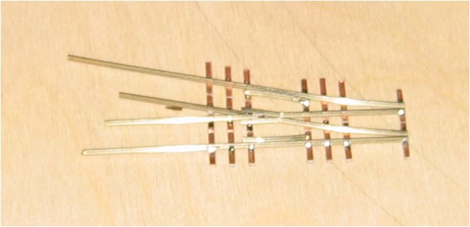 |
| Using a jeweler's saw, cut rail gaps to isolate the frog and use a continuity tester to
ensure the turnout has no dead shorts. This is a good time to clean any remaining solder flux. |
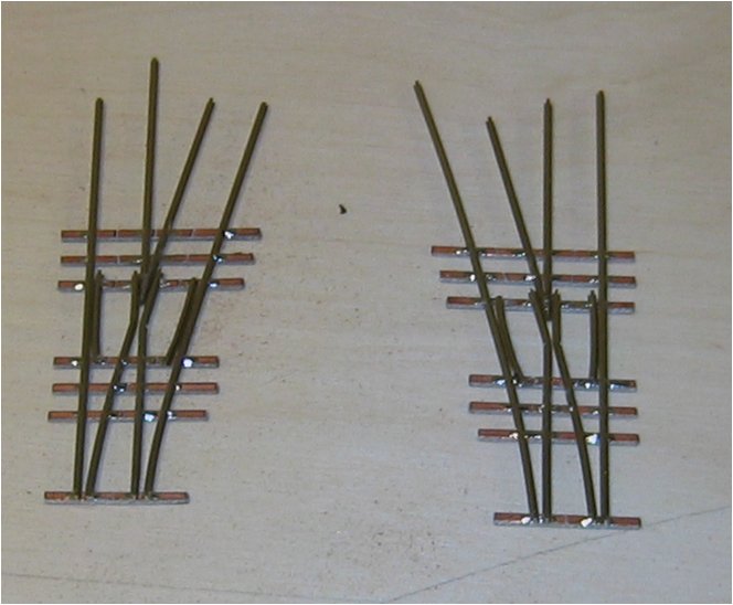 |
| Depending on where the turnout is going, adding wood ties at this point is optional. I used the plans
as a template for gluing the ties and wasn't especially worried about accuracy (it is a NG railroad after all).
This is also a good time to weather edges of the ties that are under the rails. |
 |
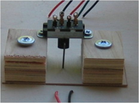
| Since I am not a big fan of using eccentrics on the layout for controlling bridle movement, I
did a fair amount of thinking and research to come up with a method for how a slide switch could
provide positive control of the bridle movement. Here's what I came up with for the switch,
here's how the turnout is wired, and
here's how the pull rods work. |

|


