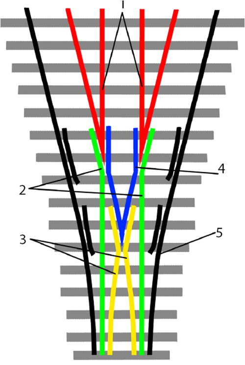
Again, the 3-way template/assembly plan is courtesy of Glen Thomas.
I added my bridle plan for a layout template in PDF. Here's how I put the
turnouts together:
| Print the pattern and attach to a piece of 1/32" aircraft plywood. Add the center line and cut out PCB tie spaces. | 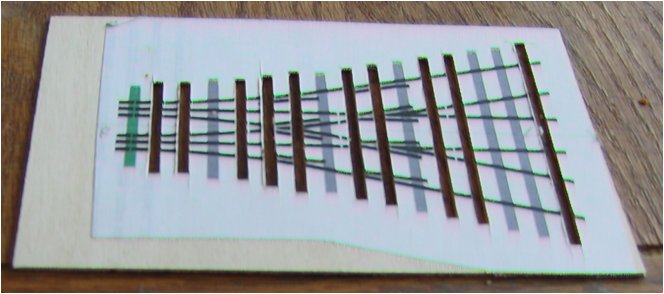 |
| Next we size and insert PCB ties. In places where a single tie won't fit, use two divided at an isolation joint. File isolation joints in other ties. | 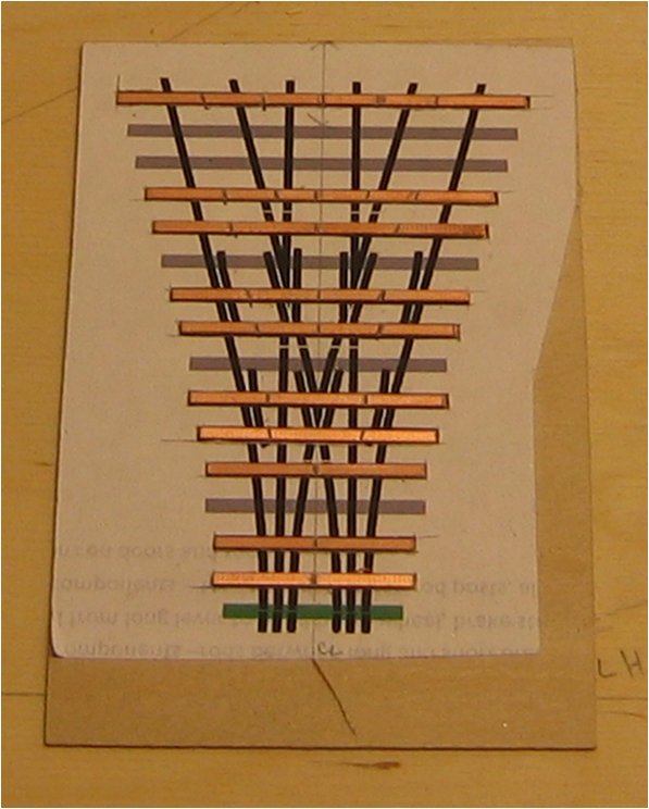 |
| Make left and right frogs using the same technique as for 2-way stubs. Arrange the frogs on the template using the center line and gauges. Tack the points onto a few of the PCB ties at this point to hold it in place. | 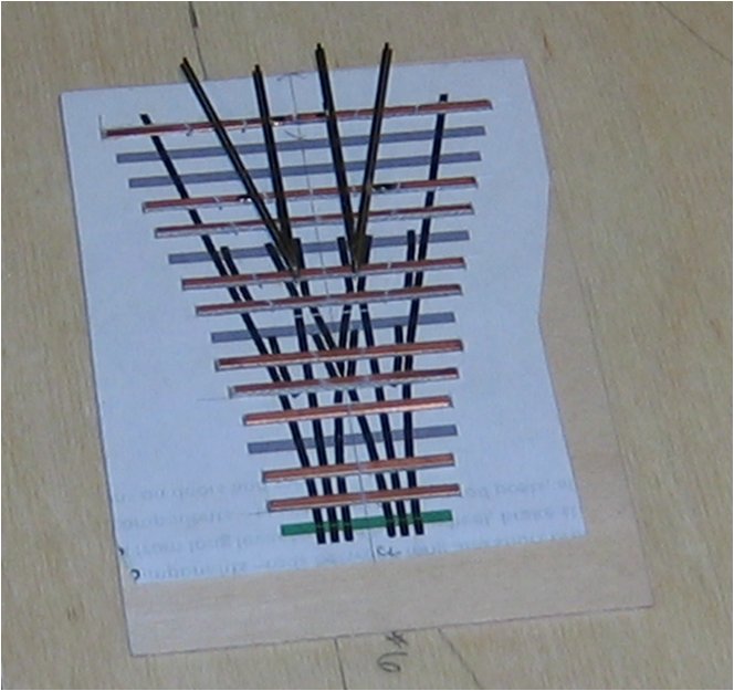 |
| Add the straight switch rails by first aligning the switch rails with the frog points and using the flange gauge to align the location of the wing rails. Again tack in place to a few PCB ties |  |
| Form the curved switch/wing rails and use the center line as a guide to align. Tack in place to one PCB tie. | 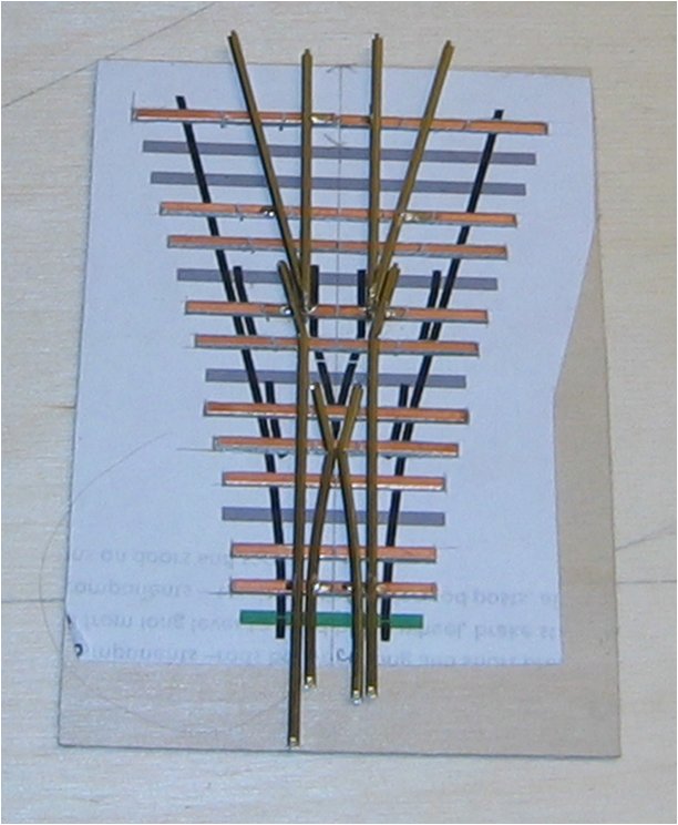 |
| Build the middle frog/wing rails in halves. Fit using the flangeway gauge and tack to a single PCB tie. | 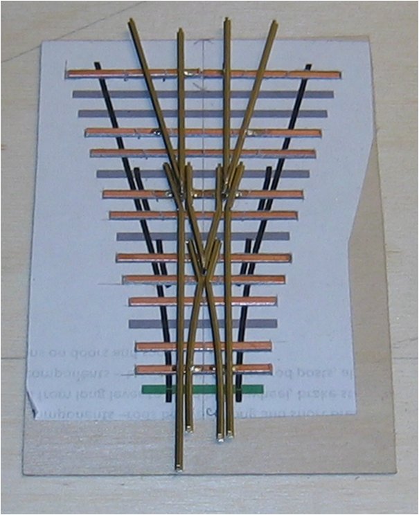 |
| Bend the stock rails to shape and tack them in place. Add guard rails, using the flange gauge to check spacing. Test each branch with standards gauge and solder remaining joints when satisfied with the fit. | 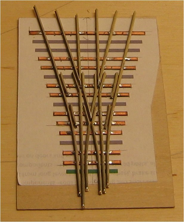 |
| Use the flange gauge to locate the head tie. After soldering the head tie in place, cut and file rails flush to the head tie. Clean flux from soldered joints. | 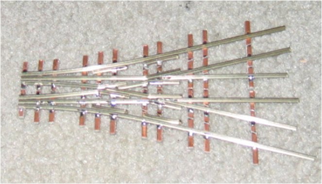 |
| I used pliobond to attach the wood ties, using the plans as a template for spacing and alignment. | 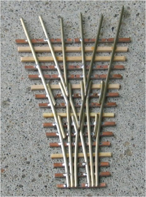 |
| Cut isolation gaps in rails with a jeweler's saw and use a continuity tester to checkk for dead shorts. | 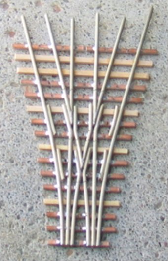 |
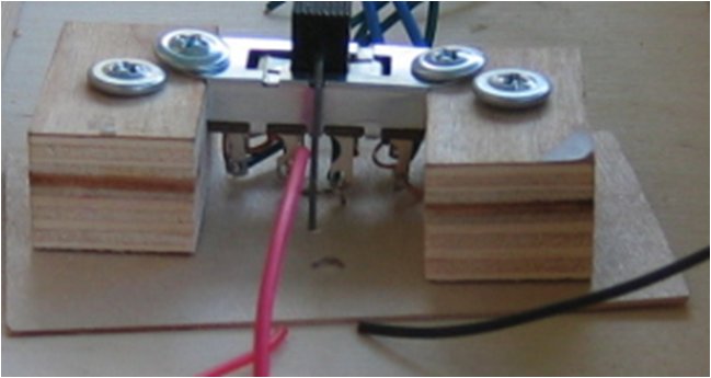
| For controlling and powering the 3-way, I used an 3-position 8-pole slide switch as shown, with the wiring shown here, and controlled from the fascia with a pull rod linkage. | 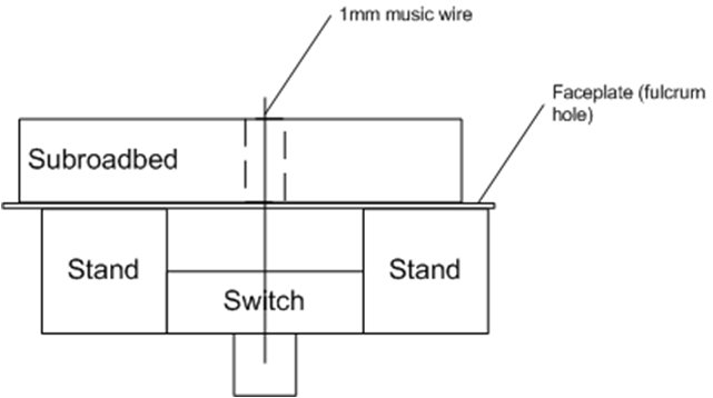
 |